Optimization of operating conditions for push-pull output stages of tube amplifiers
Optimization of operating conditions for push-pull output stages of tube amplifiers
With tube output stages connected in the push-pull (PP) design, several basic conditions are to be met for achieving optimum parameters of power transmission.
The first condition is achieving a perfect symmetry of driving signals provided by the inverter, which is connected before the output stage.
The second condition is a correct setup of bias in the output tubes. Bias value is usually recommended by the tube manufacturer for operating points in classes A, AB, and B. This article deals only with class AB push-pull output stages connected in classical or ultra-linear design.
In general, there are two methods of achieving bias for the first grids of the output tubes.
The first method of achieving the necessary bias is utilizing a voltage drop on the output tube cathode resistors (“cathode bias”). The resistors can be blocked by a capacitor, which brings the advantage of smaller required amplitude of the tube excitation voltage. If no capacitors are used, the resulting negative feedback linearizes the frequency transmission. In this case, more excitation is needed and lower power of the output stage can be achieved. However, the resulting voltage drop on the cathode resistor has to be subtracted from the total supply voltage. The supply voltage that the tubes can use to gain maximum power supplied to the output transformer thus decreases accordingly. Another characteristic of this connection is a stable amount of current flowing through the output tubes – even if they are not excited by any signal. This, of course, negatively influences the tube life.
As for the symmetry of currents in the output transformer, this connection creates a certain level of symmetry since the tubes produce their own bias. With tube aging, the current difference between the two branches of the output stage increases, resulting in greater DC saturation of the output transformer core. This influences operating conditions of the output stage and problems such as impaired frequency transmission occur (as explained below).
The second method is achieving bias from an independent source applied on the driving grids of the output tubes via adjustable resistance dividers (“grid bias”). Tube cathodes can be connected either directly to the negative pole of the power supply, or via low-resistance resistors. These resistors have several functions. They introduce a small negative feedback to the stage and so they partly compensate for splitting power between the tubes, if more tubes are connected in parallel. The cathode resistors also make it possible to measure voltage drop produced by the cathode current flowing during the setup of cathode bias for given tubes. Therefore, tube circuits need not to be opened for the purpose of measurement and setup of anode currents.
This method of introducing fixed bias allows for a full utilization of supply voltage to get maximum power of the output stage. By precise setup of the output tube operating points, absolute symmetry of DC currents flowing through both branches of the output transformer is achieved and thus a state when no DC current flows through its primary winding. These are the conditions for an optimum frequency transmission at maximum power of the stage. This is the case, however, as long as the set quiescent current in the output tubes remains unchanged. Eventually, the current starts to change over time due to the tube aging (these changes vary across the output stage tubes). As a result, an imbalance of the output stage develops gradually and DC current starts to flow through the primary winding of the output transformer. The output transformer core gets saturated with DC current, which causes performance loss and distortion of the PP stage signal transmission. In order to guarantee a smooth operation of the amplifier, it is therefore necessary to precisely re-adjust the tube operating points several times during the tube life. This method is used by most professional as well as home-made amplifiers.
There are two methods of avoiding DC current flowing through the output transformer without the need of repeated re-adjustments or replacements of tubes.
1) Using a connection that permanently controls voltage on low-resistance cathode resistors (10 Ω) and adjusts tube bias so that this voltage has a stable value independent on the driving signal of the output tubes.
The result of controlling grid bias this way resembles a connection which generates bias automatically on the cathode resistors. The difference is that for achieving maximum power, all power supply voltage can be used and the set anode currents in the output stage remain symmetrical at the same time.
2) The second method is sampling voltage on tube cathodes and comparing these values to reference voltage for bias of the first grids of the output tubes, so that the cathode (as well as anode) currents in all tubes of the output stage remain identical.
This connection behaves like the fixed grid bias, with the difference that with tube aging, the operating points shift automatically to maintain a concurrence between all currents flowing through these controlled tubes.
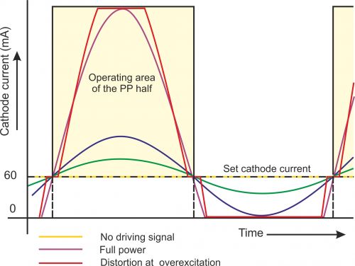
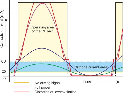
The figure demonstrates that the cathode current dynamically changes with the level of the driving signal to a large extent, but the bias remains stable. The anode current is always symmetrical in both halves of the primary winding, which ensures that no DC saturation of the output transformer (and subsequent signal distortion or performance loss) will occur. This method of grid bias control also significantly prolongs the life of the tubes in the output power stages.
Connecting the module to the output stage circuits of the amplifier.
This example uses an amplifier with EL34 tubes connected in class AB with a supply voltage of 500V.
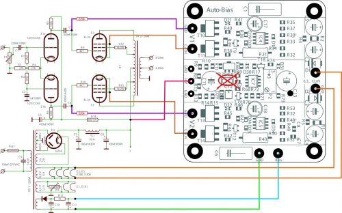
The automatic bias control module is equipped with 10Ω cathode sensing resistors. Control grids of the output tubes are connected via 100-220kΩ resistors which are not a part of the module. The P2 trimmer is used to set basic bias of both controlled output tubes. The module performs precise balancing of anode currents in the output stage and, at the same time, dynamically controls stability of the necessary control grid bias for the set currents.
For more information visit http://www.audioamp.eu