- Home
- Autobias control
- Modules adaptive bias with an supply of bias
- 230V AC autonomous automatic control bias system ABS-Q. Dimensions 100x100 mm.
230V AC automatic dynamic control bias system for push-pull (PP) amplifiers. Dimensions 100x100 mm.
Automatic optimize control bias system for triode output stages or pentode push-pull (PP) amplifiers
 amplifiers. Dimensions 100x100 mm. TES")
 amplifiers. Dimensions 100x100 mm. TES")
| Manufacturer: | TES |
| Price : | 138,00 € |
| Availability: | In stock |
Modules for to optimize bias with an supply for four triode or pentode output stages push-pull (PP) amplifiers
Designed for class A, AB, or B amplifiers.
Modules for to optimize bias with an supply of bias in four tubes.
The module is fully autonomous: requires no bias supply, powered by 230V AC mains.
The power supply part can be easily snapped off and used in another part of the amplifier.
The module is universal: it can also be fitted to amplifiers where bias is produced by cathode resistor voltage drop (cathode bias).
The module dynamically controls automatic bias settings to maintain a strict symmetry of currents through both tube branches in the output stage, and to completely avoid flow of DC current through the output transformer, all with minimum requirements on the anode current in the tubes. The DC saturates the output transformer which results in increased distortion of low-frequency sounds.
Bias control is realized by maintaining a constant bias on output tube grids, independently on the level of the driving signal.
Variable setting of the BIAS power supply -10 to -160V
The module is powered by 230 V AC mains.
User Manual ABS-Q
Automatic bias control module for four tubes
Benefits:
- No need to constantly re-adjust tube operating points
- Significantly extended tube life
- Current regulation not influenced by music signal
- Undistorted sound for a great listening experience
- Significant increase in signal clarity – extreme reduction of hum and noise level of the amplifier
- Improved bass transmission
- No maintenance or additional setup
- Optimum utilization of tube life
- Suitable for all types of output transformers (especially toroidal transformers which require automatic control)
- Perfect harmonization of both channels of the amplifier
- Safe operation due to minimized danger of runaway tube current – even when the amplifier is left unattended.
- Universal use: suitable for all connection types (even for amplifiers that are not equipped with an independent bias source)
- Fully analogous control: the module has no digital elements
The modules are suitable for all amplifier types (classes A, AB, or B), as well as single-acting amplifiers with A-class tubes connected in parallel.
Their use is strongly recommended in existing amplifiers with fixed bias of output tube control grids, as aging of the tubes causes the need for a constant re-adjustment of their operating points.
They are also suitable for fitting into amplifiers that have no bias source for controlling output stages (bias is produced on cathode resistors, usually blocked by electrolytic capacitors – in this case, such resistors are to be disconnected and the cathodes of controlled tubes connected directly to the module).
The connection secures an absolute symmetry of anode currents through both branches of primary winding of the output transformer. This way, saturation of the the output transformer core with DC current with subsequent signal distortion and dearease in available power is reliably avoided.
Furthermore, tube operating points need no further re-adjustments. The module constantly creates optimum conditions for the output stage, independently of tube aging and consequent changes in their parameters.
Setting the quiescent current through the tubes
The module is not connected in the amplifier. Apply mains voltage to TR1 terminals. Wait for the green LED (indicating the ramp up of the reference voltage) to light up. P2 trimmer is used to set the reference voltage which determines the quiescent current through the tubes. S2 jumper is connected.
Use the following formula: Vref = 0.6V, then Io = 0.6/10 = 0.06 = 60mA per tube. Vref is measured between the “Ref” point and the ground. See the figure:

As a rule, S2 jumper serves to connect the local source for generating the reference voltage on the module. If the reference voltage is to be taken from the anode supply voltage (in case of a delayed ramp up of the anode voltage, for instance), apply this voltage to HiV and disconnect the S2 jumper.
Setting the voltage of the bias source
Find the required tube bias value. It is typically specified by the manufacturer and varies depending on the connection type (classes A, AB, or B).
For instance, EL34 tubes in class AB, push-pull ultra-linear connection have a recommended bias of -45V. Place the S1 jumper to -80V position to allow a selection from -0 to -80V.
Use the P1 trimmer to set the “Bias” voltage of the checkpoint; it will be 10V lower than the required bias value (-45V-10V=-55V). This will significantly shorten the reaction time of tube parameter setting secured by the module. If you select a higher voltage value (lower negative number), the reaction time following the switch-on will be longer (as many as several minutes).
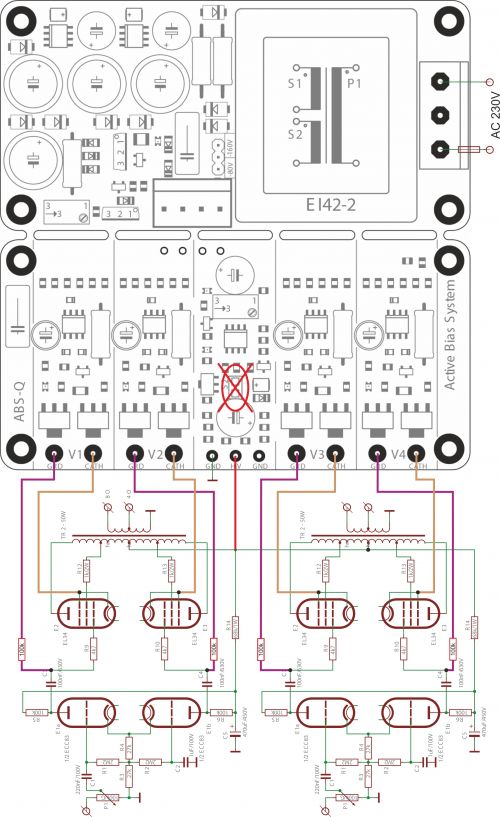
Connecting the module to the output stage circuits of the amplifier
This example uses an amplifier with EL34 tubes connected in AB class with a mains voltage of 500V.
The circuits of the first grids of the output tubes must be equipped with isolation resistors (marked red with the value 220k).
Inputs V3 and V4 are designated for the second channel. They can be, of course, used to control other tubes if connected in parallel. If the tubes connected in parallel share a cathode resistor, this common point may be used to controll all such connected tubes.
LED indication

After the module has been connected and the AC supply voltage of 230V applied, the “Soft Start” function will be initiated. The red LED located in the reference part of the module (“Soft start”) will be on for about 20 sec. At the same time, the greed LED in the bias source part of the module (“Bias on”) will light up.
After approx. 20 s, the LED will go off and the operational amplifiers of the automatic system will start to simultaneously sample the voltage of cathode resistors and set the bias for the grid bias. This process is indicated by blue LEDs (“Bias active”).
Depending on the voltage supplied by the grid bias source (P1 trimmer), the values will (about 60 sec.) stabilize after some time and the tube bias will be permanently set to unify all flows through all the four tubes. This way, saturation of the the output transformer core with DC current will be reliably avoided.
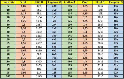
Table of resistance values of the resistor when replacing the trimmer on the AB module with a fixed resistor:
Goods of the same category - 230V AC automatic dynamic control bias system for push-pull (PP) amplifiers. Dimensions 100x100 mm.
Automatic optimize control bias system for triode output stages or pentode push-pull (PP) amplifiers The model ABS-Q+ auto bias module is designed to optimize the bias for four triode or pentode output tubes in Push-Push (PP) or Parallel-Push-Pull ...
Automatic optimize control bias system for triode output stages or pentode push-pull (PP) amplifiers Modules for to optimize bias with an supply for four triode or pentode output stages push-pull (PP) amplifiers Designed for class A, AB, or B ...