- Home
- Autobias control
- Modules adaptive bias control
- Modules for to optimize bias with an supply of bias AB-Qi-ST70- ST120 v2.0 with isolation tranformer
Automatic bias control module for DYNACO ST70, AB-Qi-ST70-ST120 v2.0 with isolation transformer
Automatic optimize bias control module for four triode output stages or four pentode push-pull (PP) amplifiers


| Manufacturer: | TES |
| Price : | 76,00 € |
| Availability: | In stock |
INSTALLATION AND USER MANUAL FOR THE AB-Qi-ST70-ST120 AUTO BIAS MODULE
Introduction:
This module has been designed to maintain a constant bias voltage through all power output tubes for your ST70 or ST120 stereo power amp.
The module contains an insulating transformer for 6.3V AC power supply for use in an amplifier where the windings for the heating tubes are grounded.
The bias is kept at a constant level on the output tubes, irrespective of the signal level.
Please note. The preset bias level for this AB-Qi module, see below for details, will differ depending on whether your ST70 uses the KT88 or EL34 power tubes.
Benefits:
The advantage of using the AB-Qi module is that it will extend output tube life, in a lot of cases it will also improve the sound and last but not least, you will never have to worry about adjusting the bias again.
- Instead of a pair of output tubes being biased together, now all four output tubes are individually biased for greater control and stability
- No need to keep an eye on and/or adjust the bias of the output tubes
- Significant extension of the output tubes life
- Bias is not influenced by the input signal
- Undistorted and improved sound for a great listening experience
- Reduction in hum and noise level of the amp
- No maintenance or additional adjustments are required after the initial setup
- Improved overall operation of the amp due to the reduction in the danger of a tube red plating
- The AB-Q ensures that bias is kept at the pre-set value (see Initial Setup) even as the tubes age
- The AB-Q comes with a soft start feature, which slowly brings up bias to each output tube
Quick Overview:
The AB-Q module has four blue LED’s, one for each output tube, which when lit, indicate that bias is at the correct level and that all is good with each tube.
Should any of these blue LED’s go out or not go on after power up, means that here is an issue with that given output tube and that the tube in question needs to be immediately replaced.
When the amp is powered up, at first a red LED will be on, indicating that there is power to the AB-Q module. The red LED will go out after about 20s.
After a further delay of between 40-50s, each of the blue LED’s should come on indicating that the bias is now set and stable for each output tube. The amp is now ready to use.
Preparing your ST70 or ST120 for the AB-Qi module installation:
It is best that you remove the driver pcb, as this will make the preparation much easier for you.
You will also need to remove original 10 OHM cathode resistors, please refer to the following photos.
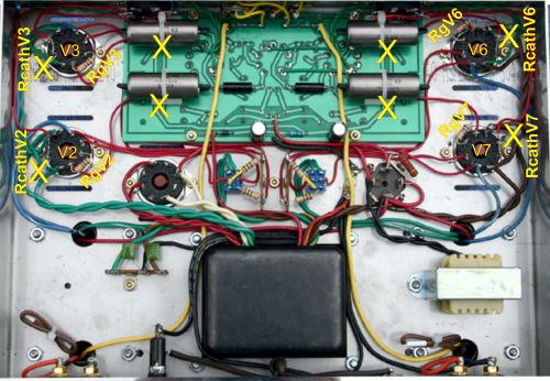
1. Remove the four 10 OHM cathode resistors marked RcatchV2, RcathV3, RcathV6 and RcathV7, connected to pins 1&8 on the four output tube sockets, marked with a YELLOW X on the photo
2. Remove wire RgV2, RgV3, RgV6 and RgV7 and remove the ST70/ST120 driver pcb
3. Remove the four original 50K bias trimmers from the ST70/120 driver pcb, marked with a YELLOW X & WHITE X
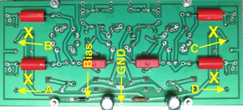
4. Solder one wire each, about 4” long, into the pcb pad indicated by the two yellow arrows marked A, B, C & D
5. Solder one wire about 4” long to the ANODE end of the bias rectifier diode D1, marked Bias on the ST70/120 driver pcb,
6. Solder one wire about 4” long to the GND pad marked GND, on the ST70/120 driver pcb
7. Do not re install the ST70/120 driver pcb yet!
8. Now refer to the ‘Presetting your AB-Q-ST70-ST120 module bias level’ section on the next page
9. If your ST70 or ST120 has the TDR time delay longer than 20sec pcb fitted, this must be disconnected. Or, use TDR with a time shorter than 20sec.
Presetting the AB-Q-ST70-ST120 module bias level:
Before the AB-Q module can be wired up, you need to preset its bias voltage.
For the ST70 or ST120 which KT88 power tubes, we recommend a bias level of 0.5V or 500mV.
For the ST70 with EL34 power tubes, we recommend a bias level of 0.425V or 425mV.
This bias level is set using the blue colored trimmer on the AB-Q module.
We strongly recommend that you preset the AB-Q module before you proceed with any of the wiring as well as before installing the AB-Q module in your ST70 or ST120!
We need to connect a 6.3VAC supply to the AB-Q module for the bias preset. If you have a spare transformer with a 6.3V winding, use that, if not, you will need to ‘borrow’ 6.3VAC from your ST70 or ST120.
If you have a spare transformer, wire it up and connect the 6.3VAC winding to the two 6,3 AC pads on the AB-Q module.
If you need to ‘borrow’ your ST70/ST120, remove ALL tubes, including the rectifier tube. All we want is the 6.3VAC from the amp, we do not want any B+ high voltage DC!
BE CAREFUL, even though all tubes are removed, there will still be high voltage AC present at the rectifier tube socket!
Solder one wire each, on pin 2 and pin 7 to power tube socket V3, and connect the other end of each wire to the 6,3 AC pads on your AB-Q module.
Place your AB-Q module on a non-conductive surface. Now switch on your ST70/ST120, or connect the spare transformer, and you should see the red LED on the AB-Q module light up. This LED will go out after about 20s.
Set your meter to read DC and to the lowest scale, say 1V, 2V or 5V. Put the black meter lead on any GND pad on the AB-Q module and put the red meter lead on the pad next to electrolytic capacitor, see below. Now adjust the blue trimmer until the desired bias level is achieved, see above for the different recommended bias levels.
That’s it, you just set the AB-Q module to the desired bias operating level.
Disconnect the spare transformer or power down your ST70/ST120, wait for half a minute or so and disconnect the wires from the 6,3 AC pads on the AB-Q module.
DO NOT EVER readjust the trimmer once the AB-Qi module is installed and wired up. The whole idea of this AB-Qi-M125 module is to set in ONCE and forget!
Installing and wiring the AB-Qi module into your ST70/ST120:
You will need to solder all the connecting wires to the AB-Q module. For neatness, solder all the wires on the underside of the AB-Q module. Make each of these wires about 7” long.
Of course, if you prefer to reinstall both the ST70/ST120 driver pcb and the AB-Q module at this stage, all the wires would need to be soldered to the top of the AB-Q module. This is entirely your choice.
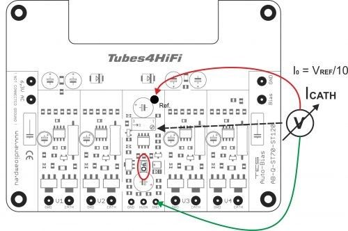
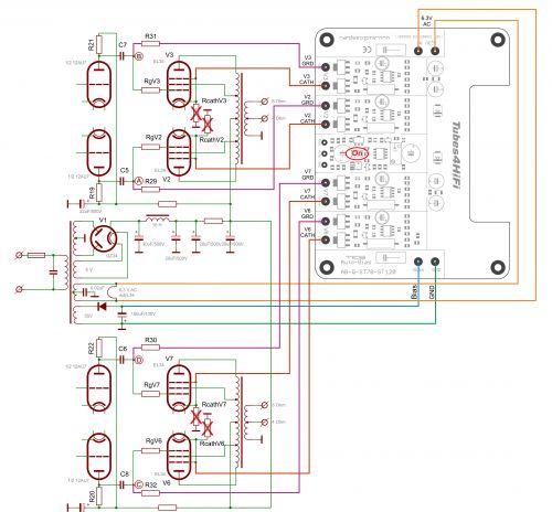
1. Solder a 7” long wire to each of the following AB-Q module solder pads: V2 GRD, V3 GRD,
V6 GRD, V7 GRD, V2 CATH, V3 CATH, V6 CATH, V7 CATH and the two pads marked 6,3 AC.
2. DO NOT connect any wires to pads BIAS, GND, V2 GRD, V3 GRD, V6 GRD and V7 GRD as yet, this is done below!
3. The wires in the two 6,3 AC pads should now be tightly twisted, as these are the 6.3VAC supply wires for the AB-Qi module and being AC, have to be twisted to ensure hum free operation!
This procedure can be a bit of a handful in trying to keep all the pre-soldered wires in check, but do the best you can J
Trim each wire to the desired length.
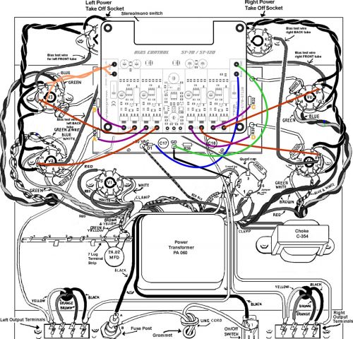
4. Connect the wire to the point indicated by the yellow arrow A on the ST70/120 driver pcb, to the V2 GRD pad on the AB-Q module, shown as a violet wire in the above wiring diagram
5. Connect the wire to the point indicated by the yellow arrow B on the ST70/120 driver pcb, to the V3 GRD pad on the AB-Qi module, shown as a violet wire in the above wiring diagram
6. Connect the wire to the point indicated by the yellow arrow C on the ST70/120 driver pcb, to the V6 GRD pad on the AB-Qi module, shown as a violet wire in the above wiring diagram
7. Connect the wire to the point indicated by the yellow arrow D on the ST70/120 driver pcb, to the V7 GRD pad on the AB-Qi module, shown as a violet wire in the above wiring diagram
8. Connect the wire from the ANODE end of the bias supply diode marked by the yellow arrow Bias on the ST70/120 driver pcb, to the Bias pad on the AB-Qi module, shown as a blue wire in the above wiring diagram
9. Connect the wire by the yellow arrow GND on the ST70/120 driver pcb to the GND pad on the AB-Q module, shown as a green wire in the above wiring diagram
10. Connect the two twisted wires from the two 6,3 AC pads on the AB-Qi module to pins 2 & 7 respectively on the power tube socket for V3, also shown as the two orange wires in the above wiring diagram. Route these AC wires away from any DC or signal wires.
The AB-Qi module kit also came with new spacers and screws. Use these to now re installed your ST70/120 driver pcb as well as the AB-Q module.
Once the AB-Qi module is installed, you can start wiring to the tubes.
Before re installing the driver pcb and the AB-Qi module, you need to connect the six 4” wires previously soldered to the ST70/120 driver pcb.
11. Re-connect the Rg1 wire from the VTA driver board to pin 6 in the V2 socket
12. Re-connect the Rg2 wire from the VTA driver board to pin 6 in the V3 socket
13. Re-connect the Rg3 wire from the VTA driver board to pin 6 in the V6 socket
14. Re-connect the Rg4 wire from the VTA driver board to pin 6 in the V7 socket
15. Connect the wire from the V2 CATH pad on the AB-Qi module to pin 1&8 in the V2 socket, also shown as a brown wire in the above wiring diagram
16. Connect the wire from the V3 CATH pad on the AB-Qi module to pin 1&8 in the V3 socket, also shown as a brown wire in the above wiring diagram
17. Connect the wire from the V6 CATH pad on the AB-Qi module to pin 1&8 in the V6 socket, also shown as a brown wire in the above wiring diagram
18. Connect the wire from the V7 CATH pad on the AB-Qi module to pin 1&8 in the V7 socket, also shown as a brown wire in the above wiring diagram
Use this diagram as a reference to the wiring of the AB-Qi module as detailed in the above steps.
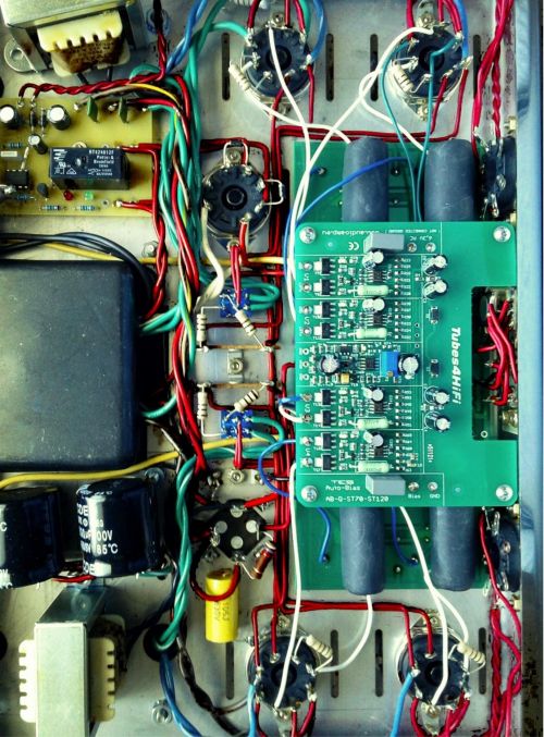
This shows the AB-Qi-ST70-ST120 module installed above the ST70/ST120 driver pcb using the supplied spacers and screws and wired up. Keep all of the above wires neat and tidy, maybe use zip ties
to group them.
This now pretty much completes the wiring of the AB-Qi module to the ST70/ST120 driver pcb and the power tubes.
Double check all the wiring steps again, even triple check them J
Once you are confident that all your wiring is correct and as per the above steps, it is time to test your AB-Qi module installation. We are assuming that you have installed the AB-Qi module into a known working ST70/ST120, not a brand new ST70/ST120 kit build, as you would need to carry out a different sequence of testing your ST70/ST120 before you should power up the AB-Qi module.
Plug in all tubes, that is the driver tubes, power tubes and the tube rectifier. In order to see the blue LED’s on the AB-Qi module, put your ST70/ST120 on its side.
Maybe stick a piece of styrofoam under one of the output transformers to cradle the ST70/ST120 chassis so that the tubes do not touch the bench top.
Connect an 8 OHM dummy load of at least 100W capacity or your speaker and if you can, short the input using a dummy RCA plug.
Power up your amp. The red LED on the AB-Qi module should come on straight away and will go out after about 20s.
After an additional 40 to 50s, each of the blue LED’s on the AB-Qi module should start to come on, which indicates that each output tube has reached the preset bias level and all is good. Excellent!
You can measure the actual bias voltage on each output tube with a meter just to double check.
Set you volt meter to the 1V, 2V or 5V scale in DC volts. Put the red meter lead on pin 1/8 on a power tube socket, V2, V3, V6 and V7 and place the black meter to the chassis star ground tag. The meter should read close to 0.5V/500mV if KT88’s are used or 0.425V/425mV if EL34’s are used. This reading might be a little higher to start with and will get close to or exactly to the preset bias voltage as the output tubes warm up.
Do this measurement for each output tube, V2, V3, V6 and V7, measuring at pins 1/8.
Leave the amp running for about 10 minutes, all four of the blue LED’s should remain lit.
Power down the amp and let everything cool down a bit then put the bottom chassis cover back on.
Remove the dummy RCA plug.
Place your ST70/ST120 amp in its spot, connect your speakers, RCA input and power lead to it and power the amp back up. After about a minute or so, the amps are ready for your listening session!
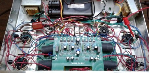
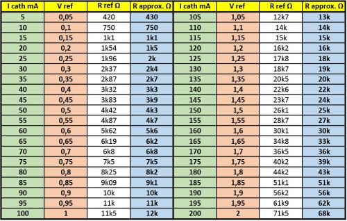
Table of resistance values of the resistor when replacing the trimmer on the AB module with a fixed resistor:
Goods of the same category - Automatic bias control module for DYNACO ST70, AB-Qi-ST70-ST120 v2.0 with isolation transformer
Automatic optimize bias control module for eight triode output stages or eight pentode push-pull (PP) amplifiers, 100 x 57 mm. The model AB-Oi auto bias module is designed to optimize the bias for eight triode or pentode output tubes in Push-Push ...
Automatic optimize bias control module for four triode output stages or four pentode push-pull (PP) amplifiers with isolation transformer. The model AB-Di-MKIV MKIII auto bias module is designed to fit the Dynaco MKIV MKIII amp chassis. It optimizes ...
Automatic optimize bias control module for four triode output stages or four pentode push-pull (PP) amplifiers INSTALLATION AND USER MANUAL FOR THE AB-Q-ST70-ST120 AUTO BIAS MODULE Download the PDF version Introduction: This module has been designed ...
Automatic optimize bias control module for four triode output stages or four pentode push-pull (PP) amplifiers. The model AB-D-MKIII auto bias module is designed to fit the Dynaco MKIII amp chassis. It optimizes the bias for two triode or pentode ...
Automatic optimize bias control module for four triode output stages or four pentode push-pull (PP) amplifiers, 123x50x18 mm (5,1"x2.1"x 0.7"). The model AB-Qi auto bias module is designed to optimize the bias for four triode or pentode output tubes ...
Automatic optimize bias control module for four triode output stages or four pentode push-pull (PP) amplifiers. INATALLATION AND USER MANUAL FOR THE AB-Qi-M125 AUTO BIAS MODULE Download the PDF version Introduction: This module has been designed to ...
Automatic opimize bias control AB-D The model AB-D auto bias module is designed to optimize the bias for two triode or pentode output tubes in Push-Push (PP) amplifiers that have their own negative bias supply circuit. Suitable for class A, AB, ...
Automatic optimize bias control module for two triode output stages or four pentode push-pull (PP) amplifiers, 88 x 50 mm. The model AB-Di auto bias module is designed to optimize the bias for two triode or pentode output tubes in Push-Push (PP) or ...
Automatic optimize bias control module for four triode output stages or four pentode push-pull (PP) amplifiers, 100 x 57 mm. Modules for to optimize bias for four triode or pentode output stages output stages push-pull (PP) amplifiers Designed for ...