- Home
- Autobias control
- Modules fixed bias control
- Automatic tube bias control system AB-4 for fixed bias
Module AB-4 for 4 tubes, PP & PPP amps, requires 6.3VAC & tube bias supply from the amps circuit, with TTL error signal output.
Module AB-4 for 4 tubes, PP & PPP amps, requires 6.3VAC & bias supply from the amps circuit, with TTL error signal output. Module ABF-Q for 4 tubes, PP & PPP & Single Ended amps, with a 6.3VAC isolation transformer for use in amps where the 6.3VAC filament supply is referenced to ground. Also requires bias supply from the amps circuit. Module AB-D for 2 tubes, PP & PPP & Single Ended amps, require


| Manufacturer: | TES |
| Price : | 88,00 € |
| Availability: | In stock |
DC current saturates an output transformer which results in increased low frequency distortions.
It is important to note that the AB-4 WILL NOT operate if the filament supply has any reference to ground, such as a center tap.
For that scenario, use the auto bias module models ABF-Q or ABS-Q+ or provide your own small power transformer of around 2VA with, for example, a 9V secondary.
- PCB dimensions are 74mm x 74mm high / 3" x 3"
- power supply requirement is 6.3 to 12VAC
- negative DC bias supply between -60V to -120V
Introduction:
This module has been designed to maintain a constant bias voltage through all power output tubes for your tube stereo power amp.
The bias is kept at a constant level on the output tubes, irrespective of the signal level.
Benefits:
The advantage of using the AB-4 module is that it will extend output tube life, in a lot of cases it will also improve the sound and last but not least, you will never have to worry about adjusting the bias again.
- Soft start indication via four red LED’s, also acting as fault indication, one for each tube
- Bias reached and steady indication via four blue LED’s
- Fault indication via TTL compatible open collector output – terminal 3 (the output may also be used for other protection outputs)
- No need to keep an eye on and/or adjust the bias of the output tubes
- Significant extension of the output tubes life
- Bias is not influenced by the input signal
- Undistorted and improved sound for a great listening experience
- Reduction in hum and noise level of the amp
- No maintenance or additional adjustments are required after the initial setup
- Improved overall operation of the amp due to the reduction in the danger of a tube red plating
- The AB-2 ensures that bias is kept at the pre-set value (see Initial Setup) even as the tubes age
- The AB-2 comes with a soft start feature, which slowly brings up bias to each output tube
Quick Overview:
The AB-4 module has two blue LED’s, one for each output tube, which when lit, indicate that bias is at the correct level and that all is good with each tube.
The AB-4 module has two red LED’s, one for each output tube, which at start up indicate ‘soft start’ for about 20s and then go off, but also double up to show any tube error or bias issue.
After a further delay of between 40-50 sec, each of the blue LED’s should come on indicating that the bias is now set and stable for each output tube. The amp is now ready to use.
The AB-4 is suitable for all amplifier types (classes A, AB, or B), as well as single ended amplifiers with class A tubes connected in parallel.
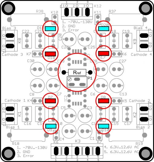
Setting the reference current through the tubes using the “Rref resistor” on the AB-4 pcb:
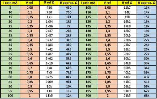
The AB-4 module is equipped with a trimmer used for setting the desired current through the tubes. This trimmer can be replaced by the customer. Prepare a standard “reference” resistor (the small leaded resistor Rref in the front part of the module as shown in the diagram below) with 3k3 resistor. This resistor produces a constant current of 38mA with 10Ω between the cathode and the ground. Below is a table of values for Rref resistor for the given current and reference voltage value.
Refer to the table below. Rref1 is the calculated value and Rref2/Rref is the closest standard value to be used. In place of the Rref resistor, the supplied multiturn trimmer may be installed. If the resistance value is too high, it can be wired in parallel with the Rref resistor to limit the amount of adjustable current.
Example: Maximum required current: 60 mA. Theoretical reference – resistor Rref, 5K62. If using the 20k trimmer, place the 5K6 resistor in parallel with the trimmer to achieve a combined resistance of 5K815 (the maximum current value is thus only 60 mA).
The circuits of the first grids of the output tubes must be equipped with isolation resistors (marked red with the value 100k) and the cathodes with 10Ω resistors.
Table of resistance values of the resistor when replacing the trimmer on the AB module with a fixed resistor:
Circuit operation:
- The reference voltage is developed across an exchangeable resistor, Rref, or an multiturn trimmer. An external potentiometer may also be used.
- The control loop adjusts the bias so that the current through the sampling resistor (10Ω) produces the same voltage as the reference voltage. This happens very slowly by rejecting the dynamic variations caused by the music.
- During startup, the Active Bias System sets the limit of distortion during this stage to just 15s. During this time the red “Start Up” LED’s are on (they may flash briefly as the control loops stabilizes).
- The Active Bias System the slowly starts ramping up the bias voltage, reaching full bias within approx. 45s.
- If a tube is faulty or fails and the desired bias level cannot be reached but it continues to receive increasing current, the relevant red “Start Up” LED will re-light and the “ERROR” output will be pulled low (open collector – output 3) to allow the external protection circuit/s, if used, to protect the amplifier from the faulty tube.
Installing and wiring the AB-4 module into your tube amp:
Please refer to the drawing below, which shows a typical tube amps connection for your AB-4 module.
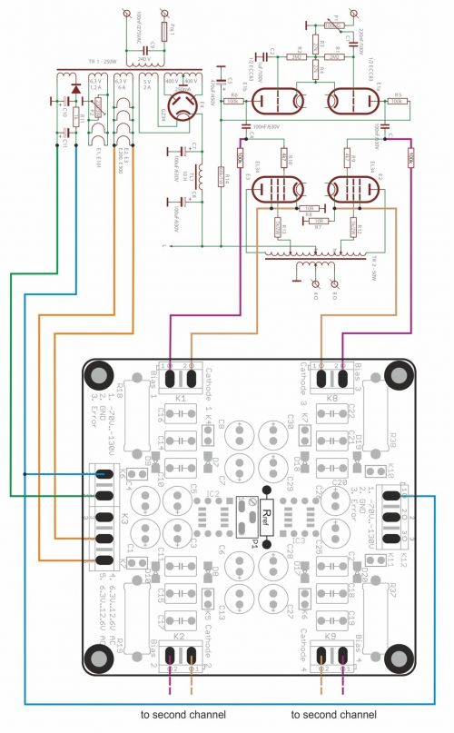
Use this diagram as a reference to the wiring of the AB-4 module into your amp. One channel is shown the other channel is identical.
- Connect your amps -ve bias supply to K3 and K12 - Terminal 1 on the AB-4, shown as a blue wire in the above drawing
- Connect a wire from your amps star ground to K3 - Terminal 2 on the AB-4, shown as a green wire in the above drawing
- Connect two wires, 6.3V to 12VAC to Terminals 4 & 5 on the AB-4 module, shown as orange wires in the above drawing
IMPORTANT NOTE about the 6.3V to 12VAC supply:
All auto bias modules without built in transformers WILL NOT WORK if the filament supply in your amp is in any way referenced to ground, such as a center tap! This important point is clearly explained on our web site!
If your amps filament supply is indeed referenced to ground, you MUST use a separate small power transformer for this AB-4 module, around 2VA, with a suitable secondary supply, anything from 6VAC to 12VAC, or use the ABF-Q module instead which has its own on-board power transformer!
- Connect a wire from terminal CATHODE 1 on the AB-4 module to the CATHODE of V1/Tube 1, shown as a brown wire in the above drawing. With almost most power tubes, this is pin 8. We also recommend that you connect the cathode of your tube, if it is a pentode, to the Suppressor grid, with most power tubes this is pin 1
- Connect a wire from terminal CATHODE 2 on the AB-4 module to the CATHODE of V2/Tube 2, shown as a brown wire in the above drawing. With almost most power tubes, this is pin 8. We also recommend that you connect the cathode of your tube, if it is a pentode, to the Suppressor grid, with most power tubes this is pin 1
- Connect a wire from terminal CATHODE 3 on the AB-4 module to the CATHODE of V3/Tube 3, shown as a brown wire in the above drawing. With almost most power tubes, this is pin 8. We also recommend that you connect the cathode of your tube, if it is a pentode, to the Suppressor grid, with most power tubes this is pin 1
- Connect a wire from terminal CATHODE 4 on the AB-4 module to the CATHODE of V4/Tube 4, shown as a brown wire in the above drawing. With almost most power tubes, this is pin 8. We also recommend that you connect the cathode of your tube, if it is a pentode, to the Suppressor grid, with most power tubes this is pin 1
- You MUST connect an isolation resistor, 100K, between the BIAS1 terminal on the AB-4 module and the OUTPUT end of the output coupling capacitor for V1 of your amps circuit, shown as a purple wire in the above diagram
- You MUST connect an isolation resistor, 100K, between the BIAS2 terminal on the AB-4 module and the OUTPUT end of the output coupling capacitor for V2 of your amps circuit, shown as a purple wire in the above diagram
- You MUST connect an isolation resistor, 100K, between the BIAS3 terminal on the AB-4 module and the OUTPUT end of the output coupling capacitor for V3 of your amps circuit, shown as a purple wire in the above diagram
- You MUST connect an isolation resistor, 100K, between the BIAS4 terminal on the AB-4 module and the OUTPUT end of the output coupling capacitor for V4 of your amps circuit, shown as a purple wire in the above diagram
This now pretty much completes the wiring of the AB-4 module into your tube amp.
Double check all the wiring steps again, even triple check them J
Once you are confident that all your wiring is correct and as per the above steps, it is time to test your AB-4 module installation.
Plug in all tubes, that is the driver tubes, power tubes and the tube rectifier. In order to see the blue LED’s on the AB-4 module, place your amp on its side.
Maybe stick a piece of Styrofoam under one of the output transformers to cradle the amp chassis so that the tubes do not touch the bench top.
Connect an 8 or 4 OHM dummy load or your speaker.
Power up your amp. The red LED’s on the AB-4 module should come on straight away and will go out after about 40s.
After an additional 40 to 50s, each of the blue LED’s on the AB-4 module should start to come on, which indicates that each output tube has reached the preset bias level and all is good. Excellent!
You can measure the actual bias voltage on each output tube with a meter just to double check.
Set your volt meter to the 1V, 2V or 5V scale in DC volts. Put the red meter lead on the cathode pin of the tube socket and place the black meter to the chassis star ground tag. The meter should read close to your preset bias voltage. This reading might be a little higher to start with and will get close to or exactly to the preset bias voltage as the output tubes warm up.
Do this measurement for each output tube.
Leave the amp running for about 10 minutes, all four of the blue LED’s should remain lit.
Power down the amp and let everything cool down a bit. Remove dummy load, if that’s what you used, or disconnect your speaker.
Re assemble your amp and place it in its spot.
Power up your amp and after about 60s or so, the amp is ready!
If things do not work as they are supposed to:
If the red LED on the AB-4 module does not come on immediately after the amp is powered up, power it back down and check the wiring/connections two 6,3 AC pads on the AB-4 module. Make sure all is good there!
If none of the blue LED’s come on after the 40-50s soft start delay, power the amp back down. Check all your wiring from the AB-4 module to your amp.
If say only three or two of the blue LED’s come on after the soft start delay, power the amp back down and check the wiring to that particular tube for which the blue LED did not go on for. Also check to make sure that the pins in that tube socket are nice and tight and that the tube fits into the socket not at all loose. Also check the pins in the tube socket of any oxidization, if they are dirty, perhaps use Deoxit or similar to clean the pins!
Do’s and don’ts:
Do check that the pins in each tube socket are tight and that each tube does not fit loosely in the socket.
Do check that the pins in each tube socket are clean of oxidization, use Deoxit or similar if they are not clean.
Good fitting and clean pins in tube sockets make ALL the difference!!
Don’t do a lot of tube rolling! This is a sure way to loosen up the pins in your sockets! If you cannot help yourself and you must do tube rolling, check the tightness of the pins each time you swap tubes!
Goods of the same category - Module AB-4 for 4 tubes, PP & PPP amps, requires 6.3VAC & tube bias supply from the amps circuit, with TTL error signal output.
Automatic bias control module for two triode output stages or two pentode push-pull (PP) tube AB-2 The model AB-2 auto bias module is a first generation design and is designed to optimize the bias for two triode or pentode output tubes for Push Pull ...